This paper was first presented at GPD 2023.
Link to the full GPD 2023 conference book: https://www.gpd.fi/GPD2023_proceedings_book/

Authors
- Ángel Mateo Marcos Núñez - ENAR. Architectural Envelopes
- Iñaki Méndez Robles - CBRE
- Jesús M. Cerezo Miguel - ENAR. Architectural Envelopes
- Miguel Ángel Núñez Diaz - ENAR. Architectural Envelopes
- Mario Hormigos Martínez - ENAR. Architectural Envelopes
Abstract
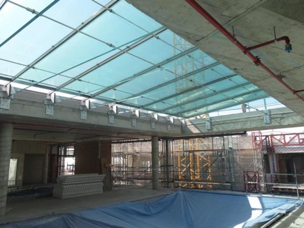
Our client CBRE architects are designing a large glass canopy within the refurbishment of the façade and MEP of a building in the prime rental area in the city center of Madrid (Spain). The new lightweight glass canopy will replace an existing heavy old one. For this, the cantilevered glass beams are structurally embedded into the metal secondary structure of the previous canopy.
Both, the glass parapet, and the glass panes that conform the floor, are fixed to the cantilevered glass beams.
The system is completed with an interior drainage channel and two bars at the ends to support lateral loads.
This paper describes the lessons learned when using structural glass to carry out the design of a canopy integrated into a new façade.
Refurbishment project and commission
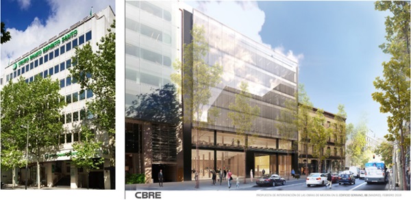
In February 2019 our client CBRE hires to ENAR for the refurbishment of an administrative-commercial building facade between adjoining properties, in Serrano Street, Madrid.
Its façade must be in accordance with the degree of luxury existing in the street where it is located. The building is property of TORIMBIA and shares the pavement with fancy shops such as YSL, LOEWE, MONTBLANC, CARTIER, LOUIS VUITTON, etc.
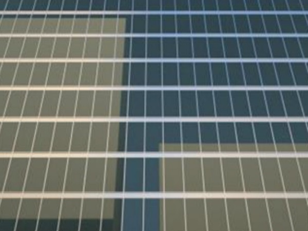
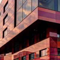
The refurbishment affects the façade, interior finishes, and MEP, together with some changes to the main structure. Several terraces and a canopy are also planned. The old stone-finished façade with small glazed openings is replaced by a one-glass insulating modern curtain wall, with a glass with vertical lines integrated in the solar control coat and with thin stainless-steel mullions.
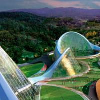
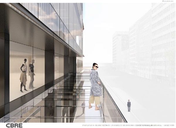
The architects decided to redesign the entrance canopy so that the volume occupied by the previous canopy could be adapted to the renovated image of the building. The renderings produced by the architects during this phase show an apparently light structure with straight lines and transparent materials.
These criteria were set out clearly defined in the project documentation during the technical design stage in order to achieve adequate competition and cost containment.
Experience and built background
Along with the architect we decided as most attractive option the use of LOW IRON glass structural elements with all edges gloss polished, laminated with Ionomer interlayer as the main structural system, which formalises the geometry of the canopy, all joined with structural silicone and stainless-steel pieces. The use of structural laminated glass elements as support of other elements has been widely used and tested, so the market of manufacturers, transformers and installers who are used to these typologies is wide enough.

For the development of this canopy project, we based ourselves on our previous knowledge acquired from admired contemporary architectures and our own previous experiences.
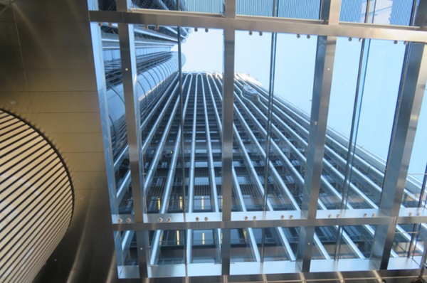
Recently we had made hybrid glass and metal beams on the entrance hall of Torre Europa GPD 2017 [1]. and for the skylight of the swimming pools of the Hotel Four Seasons Canalejas, both in Madrid.
The skylight of Four Seasons had also been executed by FERGA (façade contractor) and TVITEC (Glass supplier) which ended up making the façade and canopy of the subject building.
Criteria for the development of the canopy project
The new canopy occupies the volume left by the previous one. It is placed 5.60 m above the public pavement level, and itself 2.55 m outside the façade of the building.
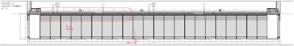
It fully occupies the 25 m width of the west and main façade of the building. As the pre-existing pillars do not follow a homogeneous modulation, it was decided to solve this situation by making a homogeneous distribution. After several tests, it was decided to use a 1.03 m between brackets, which also allowed a modulation of the floor glazing into 3.09 m wide panes between axes.
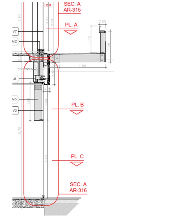
As the total height of the previous volume was 1.28 m, and brackets plus flooring pane is 0.328 m high the glass volume had to be supplemented with a railing, so it reached a top height of 1.10m above the walkable floor. It was decided to materialise this supplemented with a stainless-steel L-profile set back from the plane of the glass volume so that it remained in secondary.
Functional requirements:
The canopy must drain the water against the façade, for which it will have gutter along the joint between canopy and façade connected to the building's drainage system.
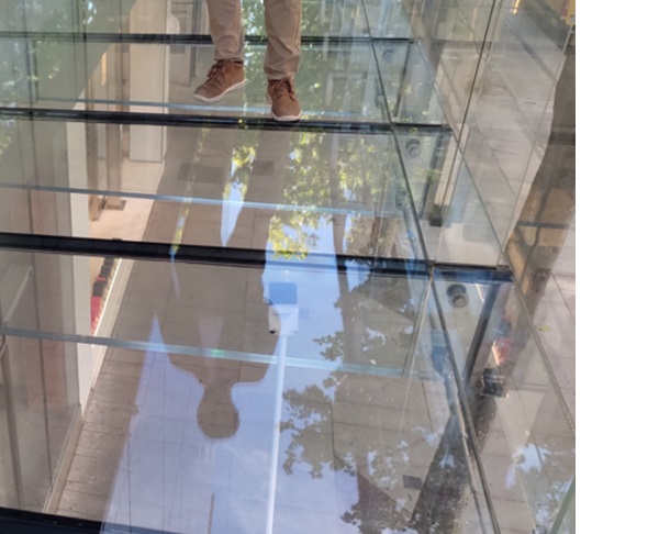
The canopy must be accessible by maintenance personnel. To this end, two access doors will be provided on the façade, a non-slip pathway will be disposed over the glazing floor along the façade and the top height of the parapet will be 1.10 m.
Structural requirements:
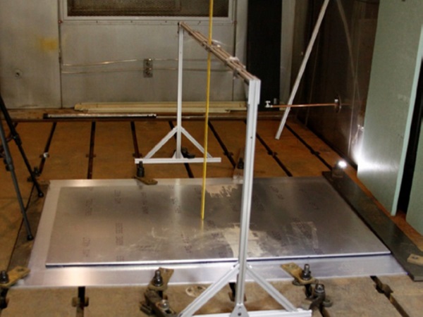
The canopy must resist horizontal wind actions, both frontal and lateral on the vertical elements (+580Pa and -840Pa) as well as vertical wind actions upwards and downwards (1100Pa and -1350Pa).
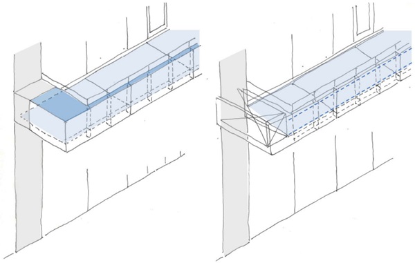
The lateral stiffening resisting system design in the project was planned to be collected by the glass vertical panes on the edges together with horizontal glazing panes disposed on the first and last module and the flooring panes, however, in this was changed by the façade contractor, and these stresses were finally transferred to the building by additional cables to metal cages that occupy the first and last modules.
Regarding to use load, calculations were made for a use overload of 500 kg/m², in addition to a horizontal live load of 0.8 kN/m, although its current regulatory use is relegated to maintenance only.
In addition, it is considered a snow overload of 0.6kN/m². In this regard, it should be noted that during the execution of the project there was an exceptional episode of snowfall in Madrid, known as storm Filomena, where several centimetres of snow remained on the canopy for numerous days.
Deformation limits were set as L/100 and 25mm for the glass forming the railing. L/500 for floor and brackets and L/150 for glass baluster. The ULS and ELS calculations were verified according to EN 16612 standard. In addition, all the structure should comply with Post-breakage safety conditions, which would guarantee the stability of the assembly after an accidental breakage of any of the fundamental glass pane that constitute the system.
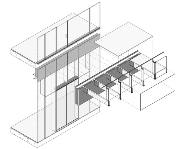
Structural composition:
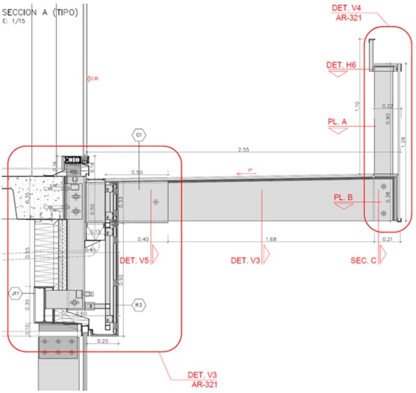
The canopy is constituted by glass brackets connected to the building by stainless-steel boxes as anchorages. Above these elements are placed glazing panes that form the flooring of the canopy. Along the front and lateral edges there is a glass railing topped with a stainles-ssteel profile.
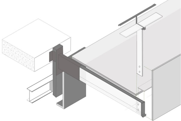
Stainless-steel boxes that act as the main anchorages are screwed on site on previously adjusted pedestals, which are supported to the slab and stabilized to an edge IPE-profile beam spaced 60 cm below. It was decided to maintain this lower edge beam because it supported the previous canopy and probed to be rigid enough.
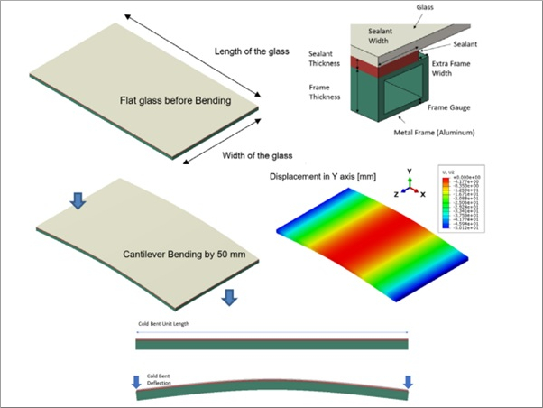
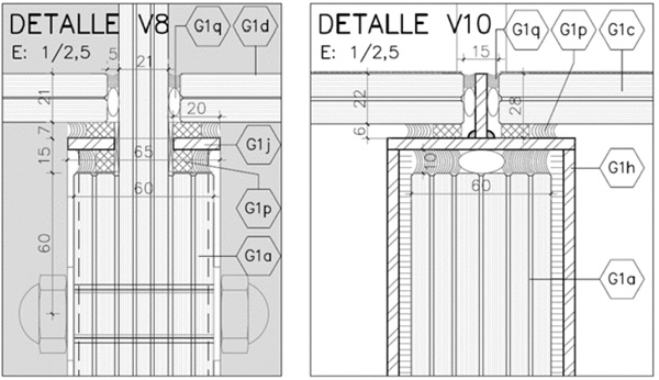
The structural engineering(MECANISMO) contracted by CBRE for this work verified the correct support of the actions on the structure. Each piece of flooring rests on 6mm thick stainless-steel plates attached to the 2.50 m x 0.3 m glass beams of composition 10T + 1.52SGP + 10T+ 1.52SGP + 10T +1.52SGP + 10T + 1.52SGP + 10T + 1.52SGP + 10T + 1.52 SGP + 10T. These pieces are horizontal on their lowest edge but inclined at the top to generate a slope that favours the evacuation of water towards the gutter disposed close to the façade and then to the interior of the building. These glass beams are confined in the workshop with resin inside stainless-steel boxes of 12mm thick plates, which have a hole with a nylon bushing that goes through each sheet of the bracket and prevents its movement.
Each 3.09m x 2.17m flooring has a 6T + 1.52SGP + 10HS + 1.52SGP + 10HS composition and is supported by 2 glass brackets along their short side and 2 glass brackets in the middle. The top sheet of glass which forms this floor has a silkscreen print that provides it anti-slip properties along a 50-cm-long strip close to the building façade to facilitate the passage of maintenance personnel. This width has been matched to the length of the stainless-steel boxes that support the lower brackets to the building.
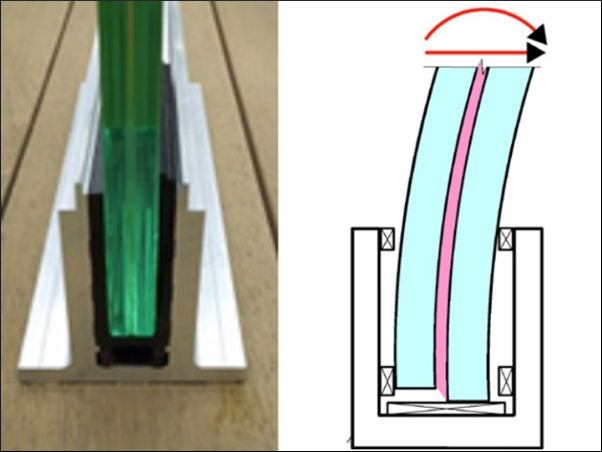
In the centre of the edge of each cantilevered glass beam, a vertical laminated glass baluster with dimensions 1.25 m x 0.15 m is screwed. These elements have a composition 6T + 1.52SGP + 6T + 1.52SGP + 6T and are topped with a metal plate that reaches the mandatory use safety height of 1.10 m with respect to the finished floor. Forming the panels of the railing and giving the final shape of the canopy there is doble-laminated vertical glass pane between the baluster.
The vertical glass panes of the perimeter railings (3.09 m x 1.28 m) have a composition of 8HS + 1.52SGP + 8HSmm and are supported by a metal plate welded to the upper plate of the brackets and adhered to its edge, while at the top they are stabilised to the glass balusters.
Conclusions
As main conclusions after the realization of the project of rehabilitation with structural glass we can obtain the following conclusions:
- The technical design stage documentation of the canopy contained sufficient definition to be put out to tender and for the actual contracting within the initial estimated costs for the project.
- The ionoplast (ionomer-based) interlayers and redundant elements were the systems used to achieve the post breakage stability.
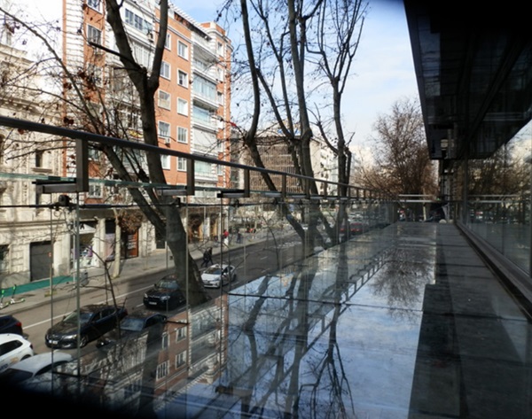
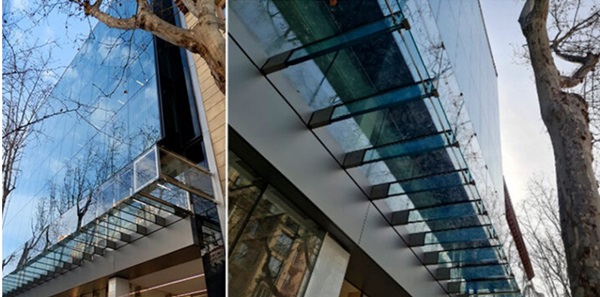
- Nonetheless a high transparency of the element has been achieved as initially intended. With an easily maintainable drain system that keeps the image of the canopy in concordance with the place where it is located.
References
[1] Nuñez Díaz, Miguel Angel & Cerezo Miguel, Jesús M. 2017 “Structural Glass in Building Restoration. Europe’s Tower Entrance Hall. Madrid. Spain” Proceedings of the Glass Performance Days Conferences, Tampere, Finland: GPD pp. 71-73.